Vacuum System Design Calculation
Vacuum system design calculation. Draw a floor plan of your shop 2. Figure System Resistance SP - Static Pressure We ALWAYS recommended you do these calculations. Approach to System Design.
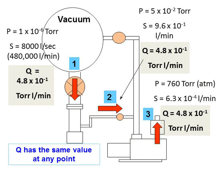
The finite element method has proven to be a very useful tool for calculating pressure distributions in complex vacuum systems. The implementation from theory to practice is shown with a system design based on an example. Determine Diameter and CFM of each Branch 4.
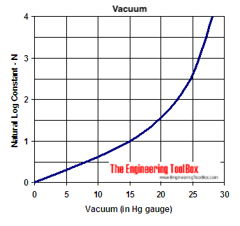
T V q ln p0 p1 1 where. It is now a well-established practice and is primarily concerned with the prediction and calculation of how vacuum pumps and. 2 m and an uniform thermal outgassing rate q in mbarlscm.
Let A be the specific surface of the vacuum chamber in cm. Pressure relief valves to be incorporated where a vacuum system can be vented to 10 kPa above atmospheric pressure. Analytical Solution Periodic System Consider a simple vacuum system of uniform cross section with lumped pumps installed every L meters apart no distributed pumping.
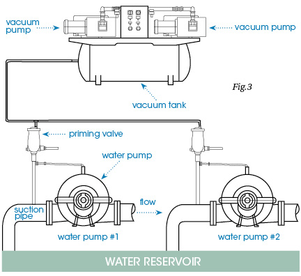
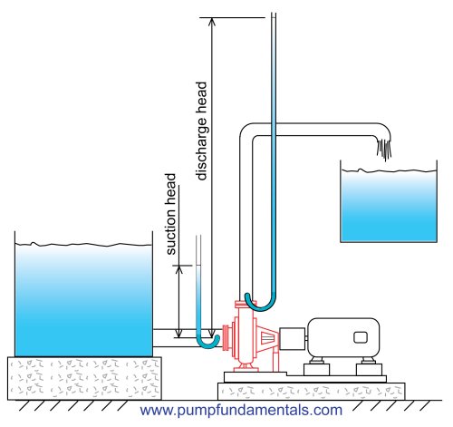
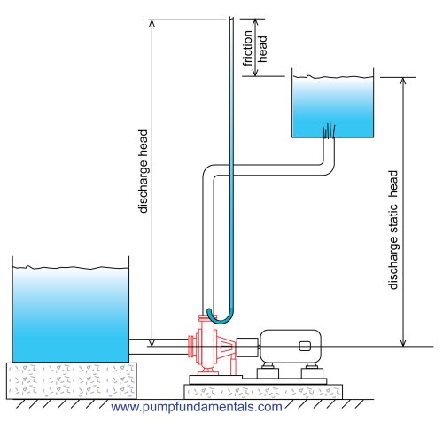
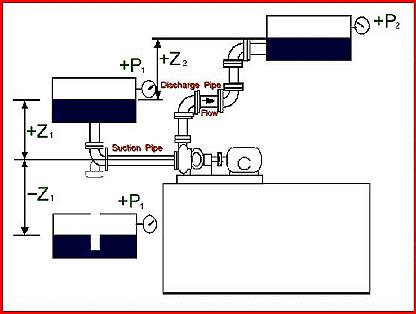
For example it can enhance a pumping system by reducing the load on an existing motor. Imagine for instance pumping a liquid from one level up 80 ft to a vessel operating under vacuum. Vacuum technology is based upon the creation of an environment in which a process thin film deposition electron beam welding etc can be carried out.
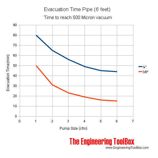
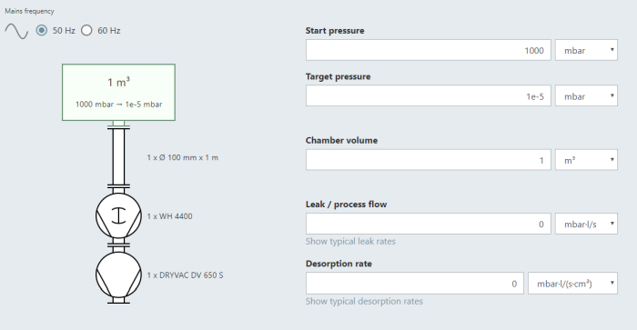
The evacuation time for a vacuum pump can be calculated as. The vacuum engineer is concerned with the efficient removal of adsorbed surface gas. Determine Duct Velocity FPM 3.
Table 1 The diameters of some molecules Molecule Diameter Å Ar 32 CO 41 He 19. The only difference is the mass flow generated by a compressor in vacuum mode or pressure mode.
Some of these factors will be discussed in Sections 2231 and 23.
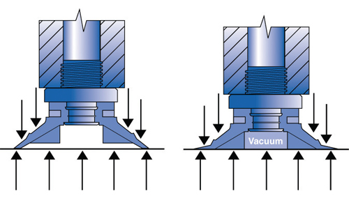
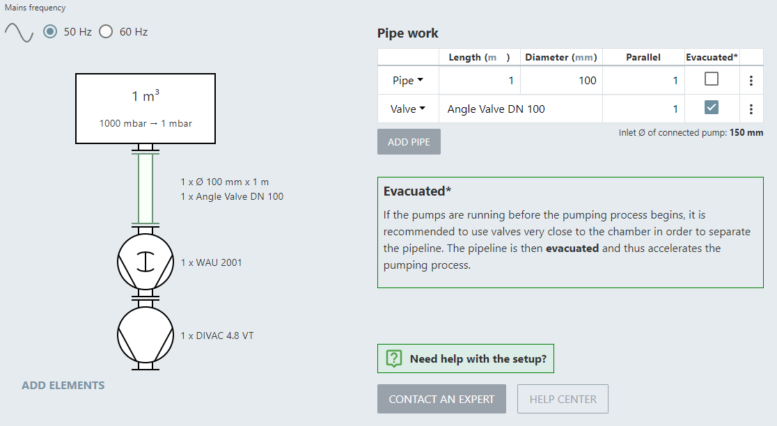
T evacuation time s V enclosed evacuated volume m3 cuft q volume flow rate capacity of the vacuum pump m3s cufts p0 initialization pressure - normal atmospheric pressure mbar mmHg. Determine Diameter and CFM of each Branch 4. Forall subsequent calculations it isimportant to know the massof the workpiece to be handled. The implementation from theory to practice is shown with a system design based on an example. Home Vacuum Knowledge The Vacuum System and its Components System-Design - Calculation Example. T evacuation time s V enclosed evacuated volume m3 cuft q volume flow rate capacity of the vacuum pump m3s cufts p0 initialization pressure - normal atmospheric pressure mbar mmHg. However both these values are not known. Analytical Solution Periodic System Consider a simple vacuum system of uniform cross section with lumped pumps installed every L meters apart no distributed pumping. The finite element method has proven to be a very useful tool for calculating pressure distributions in complex vacuum systems.
2 m and an uniform thermal outgassing rate q in mbarlscm. M 25 x 125 x 00025 x 7850 m 6133 kg xample of Vacuum calculation System design - the procedure. The molecular diameters in Ångström 1ÊÅ10-8Êcm of some gases commonly found in vacuum systems are given in Table 1. Vacuum system calculation and simulation services. Conductance limiting components surface outgassing rates and leak rates in order to design the most cost-. It is now a well-established practice and is primarily concerned with the prediction and calculation of how vacuum pumps and. Motivation The goal is to develop a numerical model of the vacuum system whether simple or complex.

















Post a Comment for "Vacuum System Design Calculation"